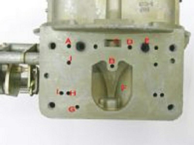
Holley two-circuit metering block

(B) Idle downleg:
This passageway feeds fuel to both the idle discharge port and the idle transfer slot.
(C) Idle well:
Fuel from this well travels to the top of the metering block, then turns 180 degrees and mixes with air from the idle air-bleed into the circuit.
(D) Accelerator pump passage:
This transfers fuel from the accelerator pump to the outlet nozzle.
(E) High-speed air-bleed:
Air from the high-speed bleed enters the metering block here to be mixed with the fuel as it climbs the emulsion tube.
(F) Passage to booster:
This channel transfers fuel from the main well to the booster
(G) Ported vacuum passage:
This connects the ported vacuum source in the throttle body to the outlet where this can be routed to a source like vacuum advance.
(H) Parallel air well:
Air is introduced into the main well through these two holes.
(I) Main well:
Fuel collects here after passing through the main jet.
(J) Power valve channel:
This is where the power valve is located. The two small holes are the power valve channel restrictors (PVCR) that determine the amount of fuel added to the main metering circuit when the power valve opens. This valve determines when additional fuel is added to the main circuit.
(K) Idle restrictor channel:
Fuel from the main circuit passes through this short channel and through a small brass restrictor (L) that acts as the idle circuit jet.
(M) Idle transfer slot discharge:
Idle fuel exits the metering block to deliver fuel to the transfer slot.
(N) Idle fuel discharge port:
Idle fuel exits the metering block and enters the carburetor main body for carb idle fuel below the throttle blades.
(O) Dowel pin:
Two pins locate the metering block on the carburetor main body.
Bowl Side of Metering Block
(A) Timed spark port:
This outlet supplies ported manifold vacuum for distributor vacuum advance only
after the throttle is opened slightly.
(B) Vent whistle:
This plastic vent piece vents the float bowl area and also prevents fuel from
splashing into the primary venturi under hard acceleration.
(C) Idle mixture screw:
This adjuster screw meters the amount of fuel and emulsified air delivered to
the engine at idle.
(D) Accelerator pump entry point:
This is where the fuel from the accelerator pump enters the metering block,
traveling up that adjacent diagonal port to the center hole on the opposite side
of the metering block.
(E) Main jets:
These are the replaceable main jets used to trim the main metering system.
(F) Power valve:
Fuel enters the power valve enrichment circuit from the float bowl.
(G) Other idle mixture screw:
This adjuster screw meters the amount of fuel and emulsified air delivered to
the engine at idle.
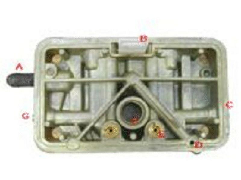
Carb Main Body
(A) Idle air passage:
Air from the idle air-bleed enters the metering block here.
(B) Accelerator pump discharge passage:
Fuel from the accelerator pump enters the main body of the carb here and travels up to the squirter.
(C) Fuel bowl vent:
This vent places atmospheric pressure on the fuel in the float bowl.
(D) High-speed air-bleed passage:
This is where air from the high-speed air-bleed enters the metering block.
(E) Booster venturi inlet: Emulsified fuel from the main well enters the booster through this passage.
(F) Power valve vacuum well:
Intake manifold vacuum is present in this cavity. When the throttles are opened and vacuum drops off in this well, the power valve opens.
(G) Timed spark port:
This hole delivers manifold vacuum only after the throttle is opened past curb idle. This is normally the outlet port for vacuum advance.
(H) Idle transfer slot to discharge:
This port delivers fuel to the idle transfer slot in the throttle body that is uncovered under light throttle.
(I) To curb idle:
Idle fuel enters here from the metering block to the curb idle discharge point on the throttle body.
(J) Auxiliary air:
This hole is used only with an auxiliary idle air-bleed circuit.
Throttle Body

(A) Power valve vacuum
port:
This connects the manifold vacuum to the power valve. This is also where newer
Holley carbs are fitted with a blowout protection check ball to protect the
power valve.
(B) Full manifold vacuum source:
Outlets for constant manifold vacuum.
(C) Primary throttle blades:
All air flows through these blades at part throttle up to a given percentage of
throttle opening.
(D) Curb idle speed screw:
This sets the idle speed on the primary side.
(E) Secondary throttle blades:
Controlled by either mechanical or vacuum actuation.
(F) Secondary throttle stop:
Small adjustment screw that is a stop for the secondary throttle blades.
(G) Curb idle transfer passage:
Machine passage for idle fuel discharge to secondary side with two-port idle
mixture screws for more even idle fuel entry into engine.
(H) Idle transfer slot:
This is where idle fuel enters as the primary throttle blades are opened for
part-throttle operation.
(I) Full manifold vacuum source:
Outlets for constant manifold vacuum.
(J) Curb idle discharge:
This passage leads to the small hole underneath the throttle blades where the
idle fuel enters the engine.