REFRESH YOUR PAGE with F5 so you know you have the latest updates
Last Updated:
Oct 22, 2015 - Added note about the input shaft cage with needle bearings during the install.
and updated step 18 in the Transmission Assembly section near the end.
Each time I do a rebuild on someone's trans, if I find something easier to do
I'll make a change in the document.
Click on thumbnail to enlarge
I've taken pictures as I went as long as I had a free hand. There were some that I missed
and some I had to use that were close to the steps below.
Some pics I had to use 2 to create 1 in Corel. Also if I need to I'll use my M20 parts for some photos.
Tools needed to make the job easier. If you have any questions, don't hesitate to ask.
All gaskets and bolt threads were treated with Permatex 2. Happy building.
![]()
![]()
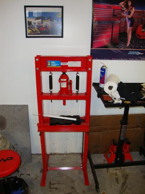
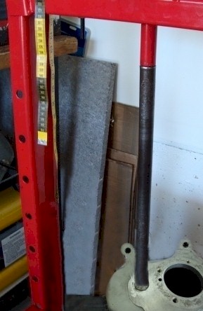
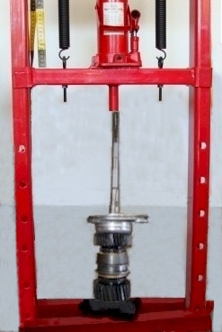
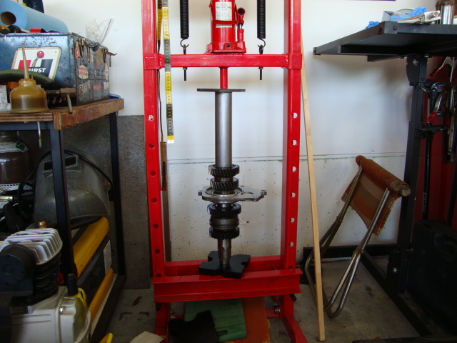
Hydraulic press with 12 Ton bottle jack cost me $99.
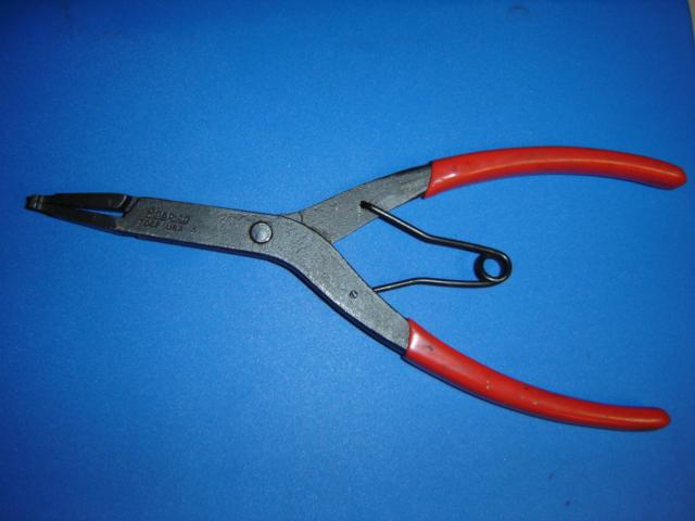
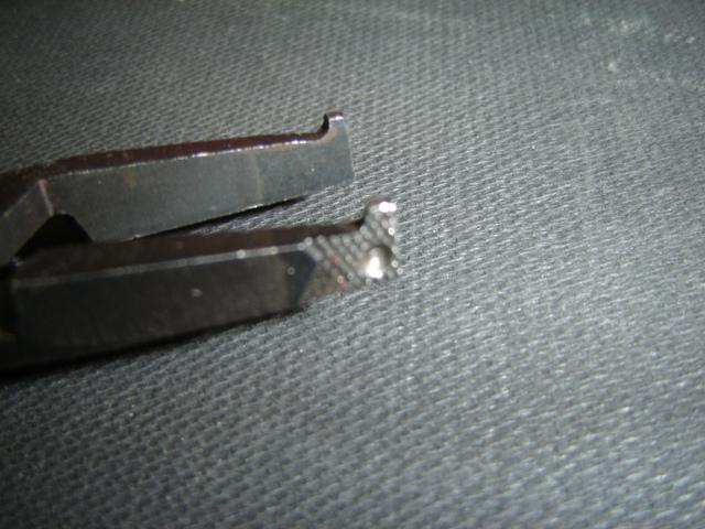
Snap-on model 70CP pliers.
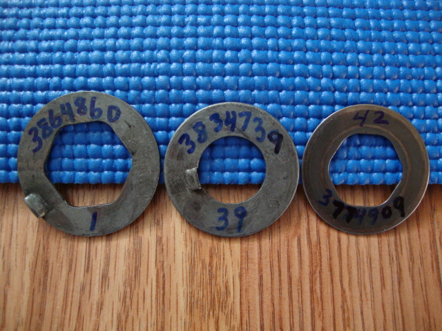
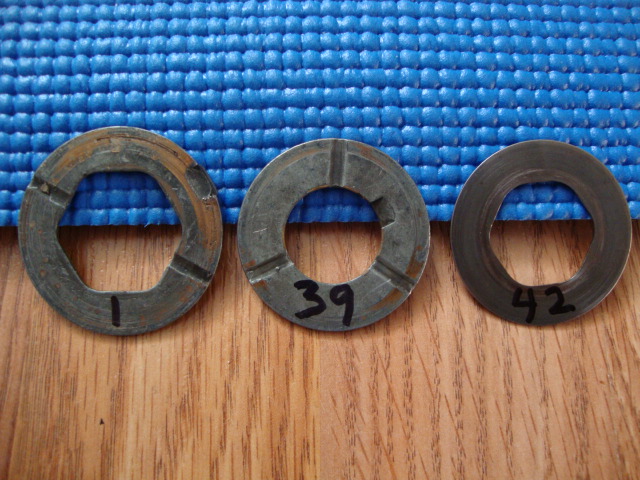
GM Washers part # and # from the exploded view. LINK
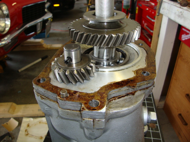
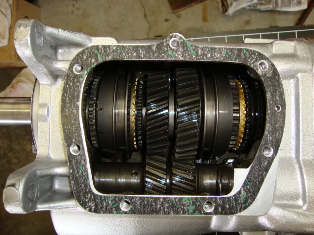
Disassembly:
1. Drain the oil into a container. Check oil color, and also, for metal deposits.
This would help in diagnosing defective parts. For instance oil with a bright
yellow color would indicate badly worn synchromesh blocking rings.
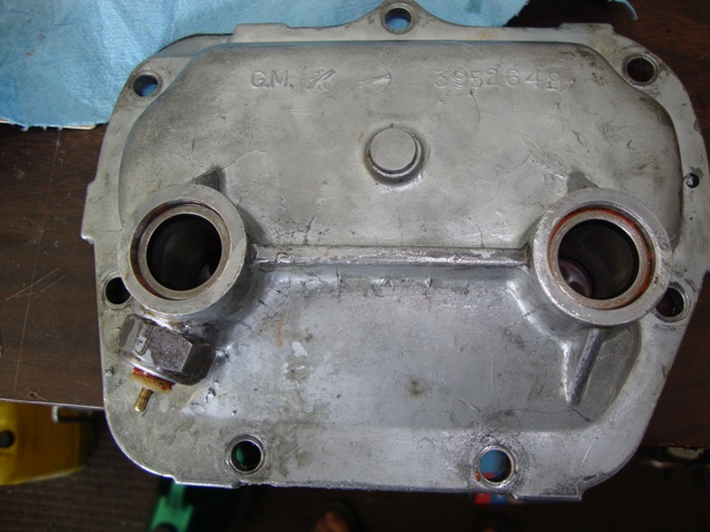
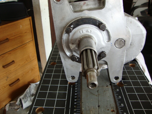
2. Shift side cover into 2nd gear. Use 1/2 inch box wrench and remove
seven (7) 5/16 x 7/8 inch bolts that secure shifter side cover assembly
to the transmission case. Remove cover and gasket.
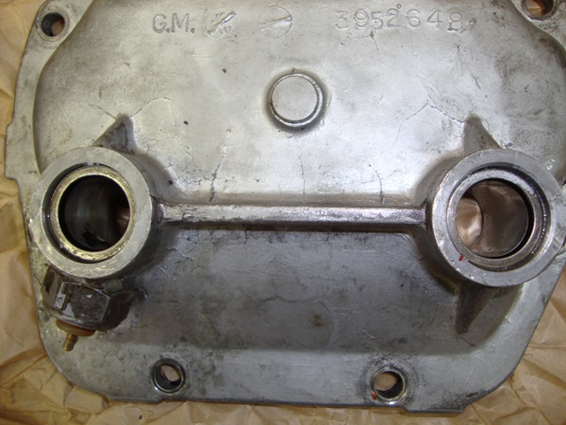
3. Use 9/16 inch box wrench and remove four (4) 3/8 x 7/8 inch bolts that
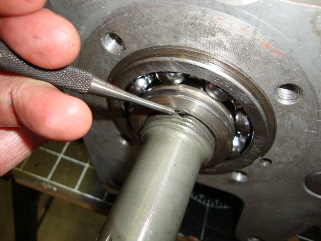
secure main drive gear front bearing retainer to the case. Remove retainer
and gasket.
4. Manually lock-up transmission (place into two gears).
I have it in 4th and 2nd. Use your fingers to slide the slider into the 2 gears.
Your fingers are the forks here.
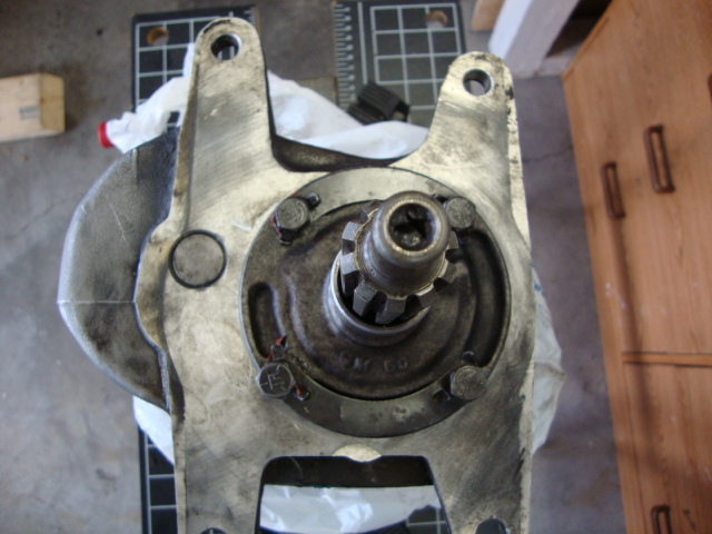
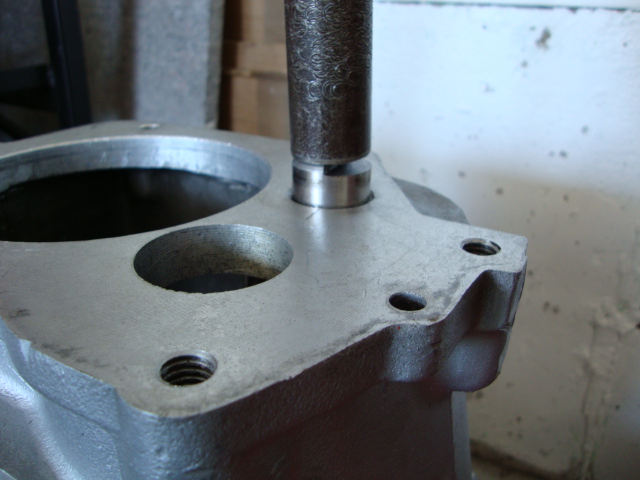
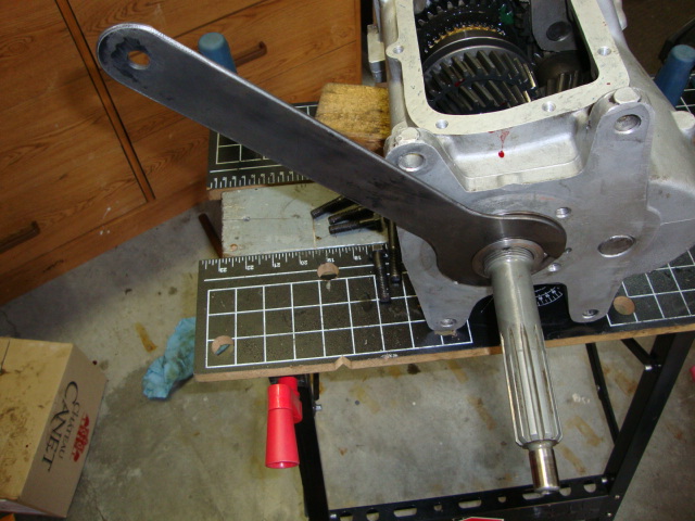
5. Place transmission in neutral then shift into 4th gear. Using tool J-933 (avail on eBay)
or similar, remove the main drive gear retaining nut. Note: nut is removed by turning clockwise.
Since the nut is stacked, (see 2nd pic in step 3), I ended up using a pipe wrench to get
it to start turning. Damaging the nut is ok since your going to replace it with a new one.
If your reusing the front bearing due to it still being new then don't allow the pipe wrench
to touch it or scuff it. I didn't take a photo of the nut when I removed it but I added the
photo when I installed a new nut. but this isn't staked yet. I just needed a photo.
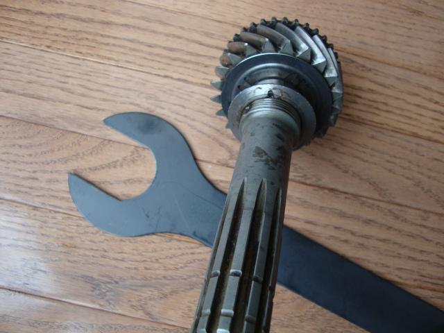
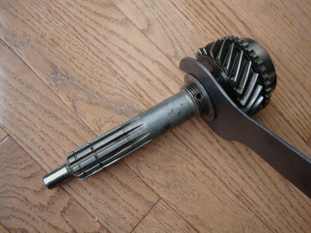

J-933 nut tool I bought from eBay.
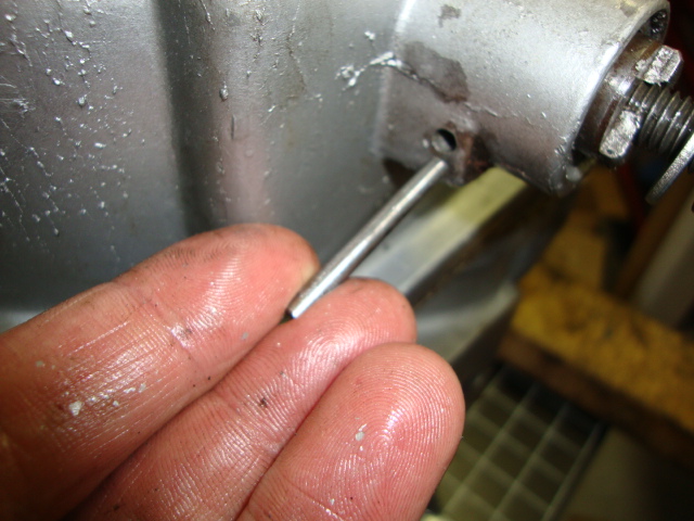
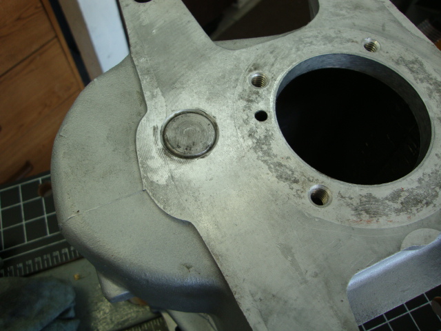
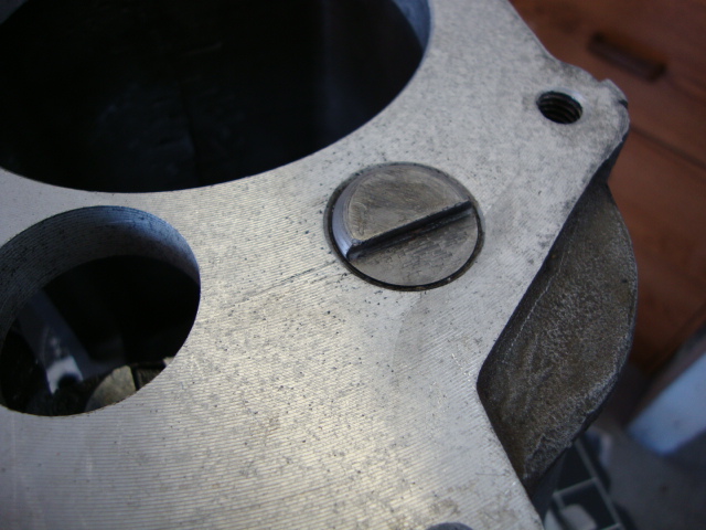
6. Use 3/16 inch drift punch and remove reverse shifter shaft tapered lock pin. Note: pin is
removed from the bottom.
Note this pic was taken when I was installing it. It installs from the top but gets removed
by tapping it on the bottom.
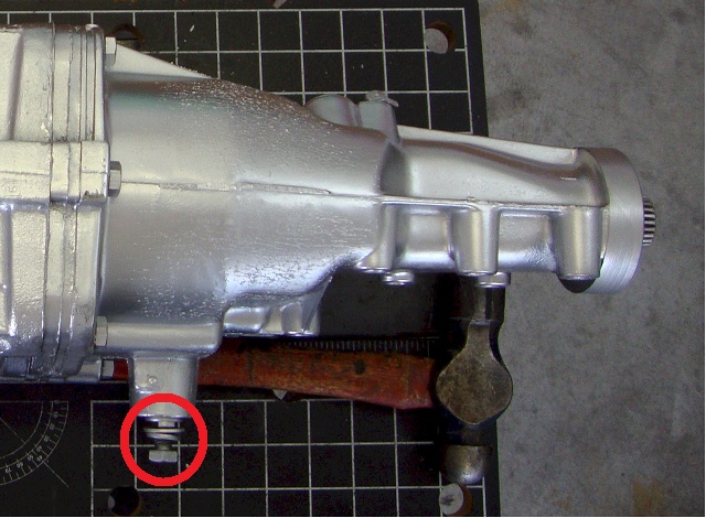
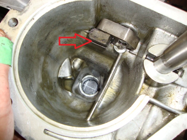
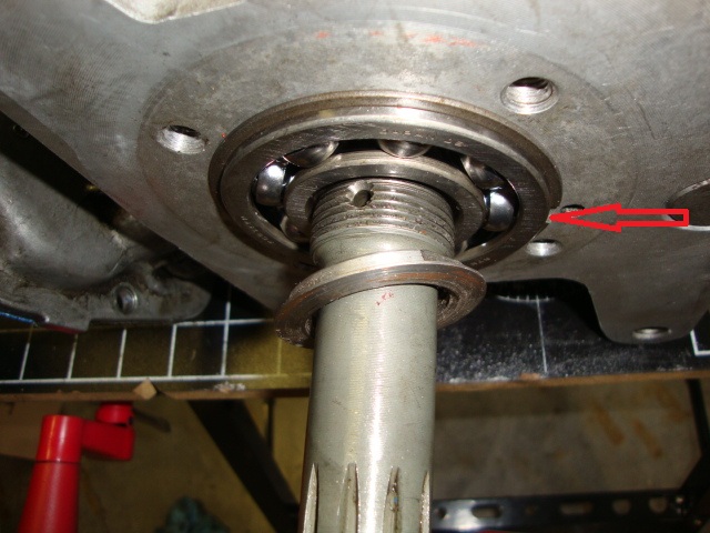
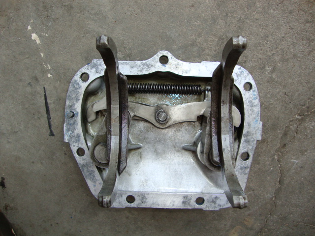
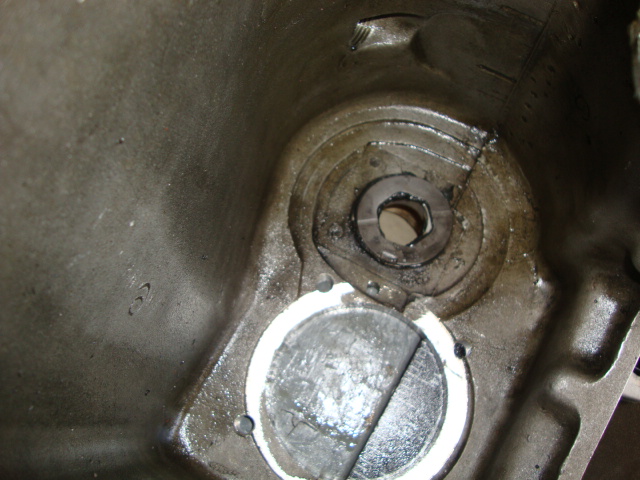
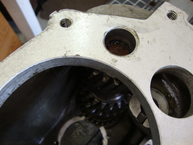
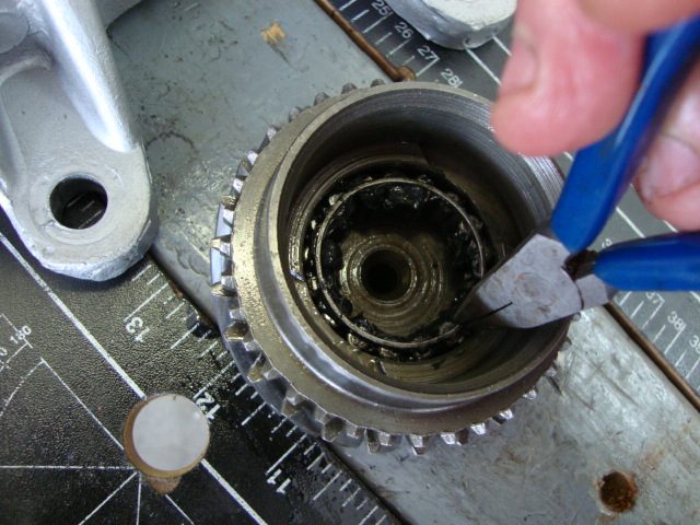
7. Disengaging Reverse: After removing the pin, use pliers and pull out the shaft that's circled in
red below until it disengages reverse gear.
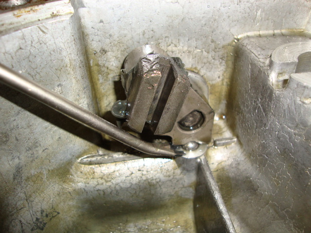
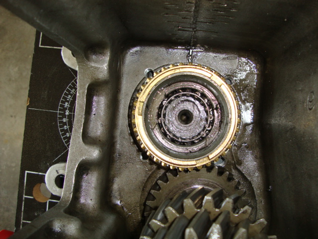
This is what's going on inside when you pull the reverse shaft. The arrow in the left photo below
shows the slotted reverse arm in its correct position for it to fit into the edge of reverse gear.
See arrow also in the 2nd photo below.

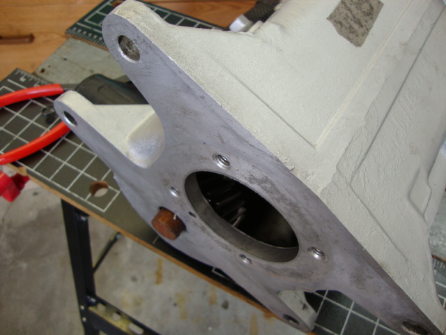
8. Tail Housing: Use 9/16 and 5/8 inch box wrenches and remove three (3) 3/8 x 11/2 and
three (3) 7/16 x 11/2 inch bolts that secure extension housing to the transmission case.
Pry back extension housing off the dowel pins.
Rotate housing while removing to clear the reverse fork from the gear. Then push the lever
back in until you can slide the old lock pin back in. This will stop the reverse rod from
accidently coming out too far and popping the steel ball out of it's groove. If you accidently
pull the shaft out too far when your cleaning things and the ball drops out, you'll need to use
something angled to push on the ball in a downward force while trying to slide the
reverse lever back into it's groove position.
See photo of what I used to force the ball down while pushing the arm towards the case.
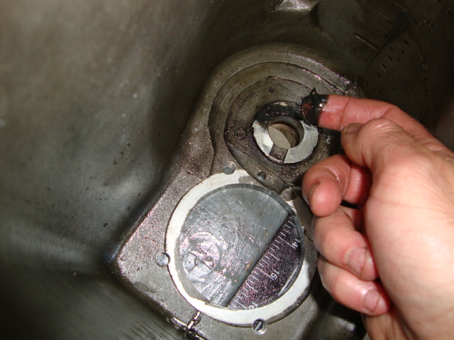
9. Remove speedometer drive gear. Mines plastic with a locking clip that has a hole. If yours is steel
then make a line or measure where it's currently sitting. Then you'll need to press it off.
I have heard some heating the steel speedo gear when they are ready to slide it back on during the
assembly. Note clip orientation in Diagrams Section too. I did notice that when I tried installing the
clip the other way that the plastic gear was not fully visible from the speedo bullet hole from the
outside of the case.

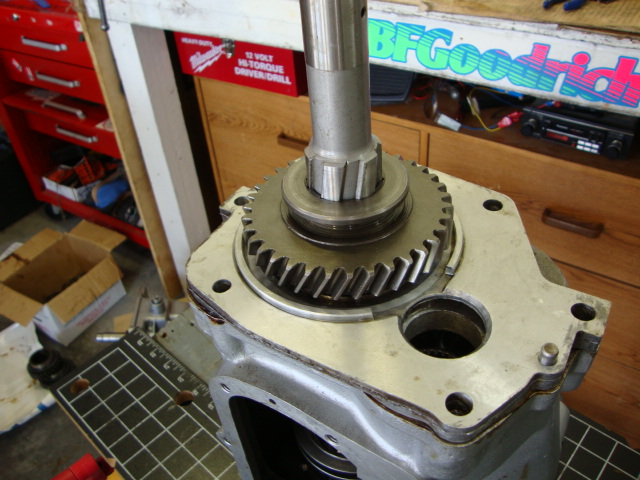
10. Remove reverse gear and note which is facing the top for reassembly.
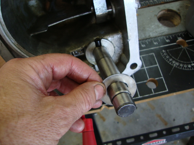
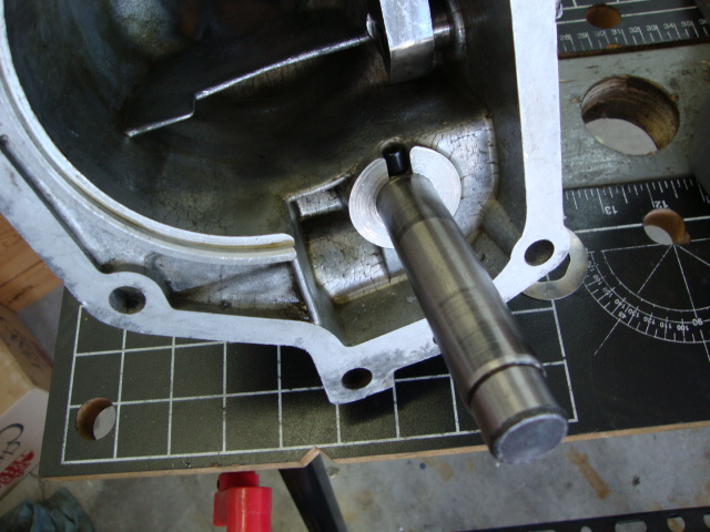
11. Remove reverse idler rear gear (1st pic below), then the thrust washer (2nd pic) and shaft
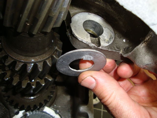
(3rd pic). Note the rear washer does not have a tang like the front washer. Leave the pin in the shaft.
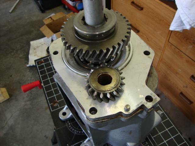
12. Remove the front reverse idler gear and thrust washer from the main case. Note tang on this
washer that goes into the slot. Grease or Vaseline holds it in place on assembly.

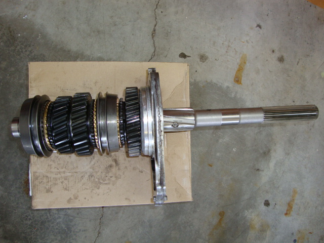
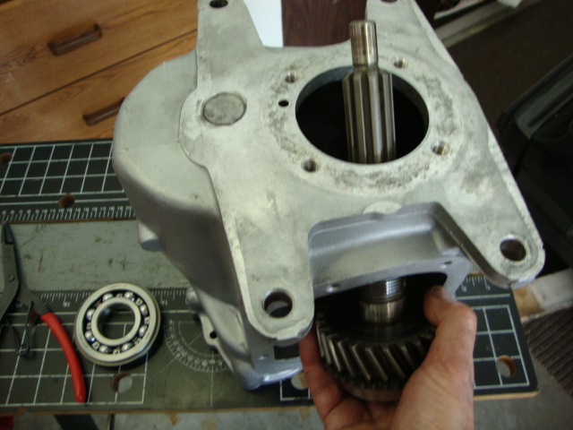
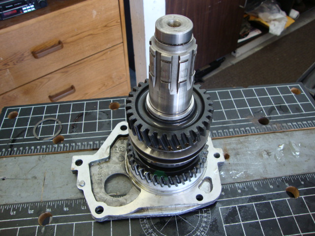
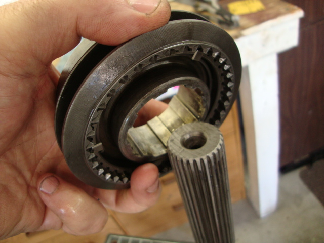
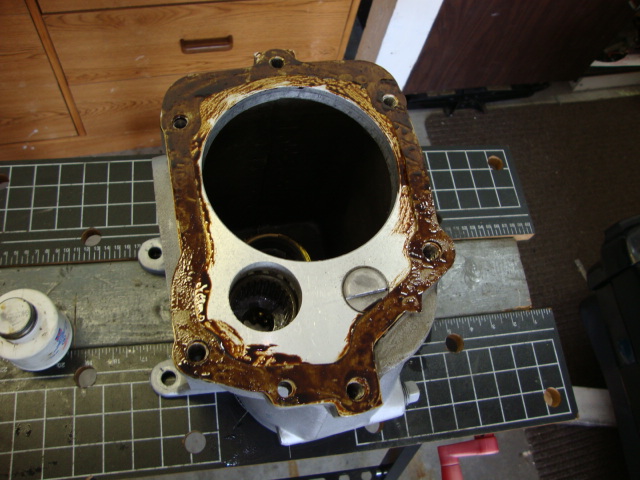
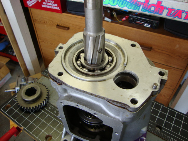
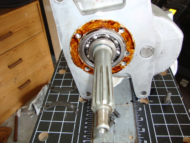
13. Remove main shaft, rear bearing retainer with bearing from the transmission case. Maneuver as
necessary to remove. You may hear the input shaft (4th gear) needle bearings and cage fall out.
Not to worry, keep the cage if a new one is not supplied in the rebuild kit. The needle bearings
can be replaced.
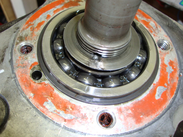
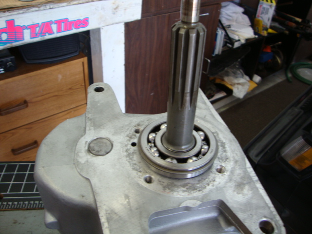
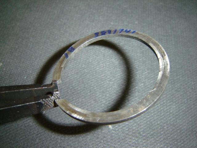
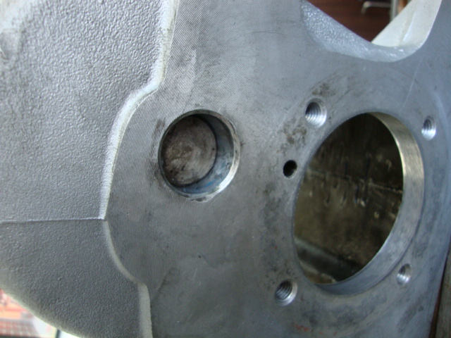
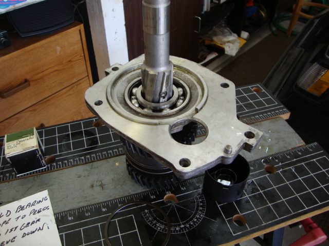
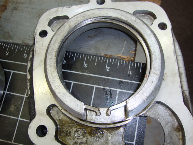
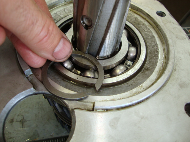
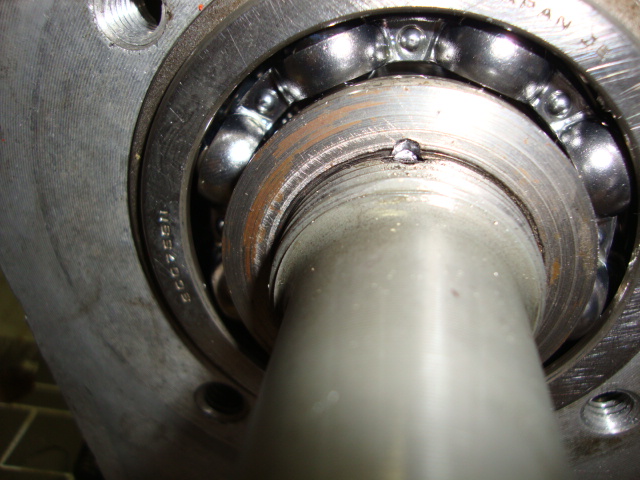
14. With the lock nut already removed from the input shaft from previous steps, leave the snap ring
on the front bearing and tap on the input shaft front so it comes loose in the case.
If the shaft is tight on the bearing then take the case to the press and press it out.
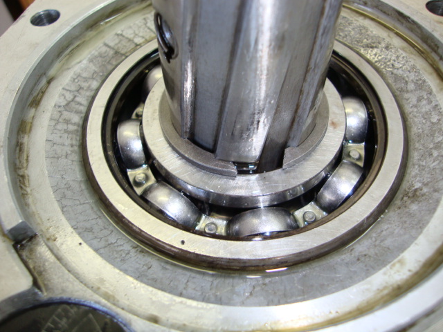
You should now be able to tap out the front bearing form the inside with the snap ring still on.
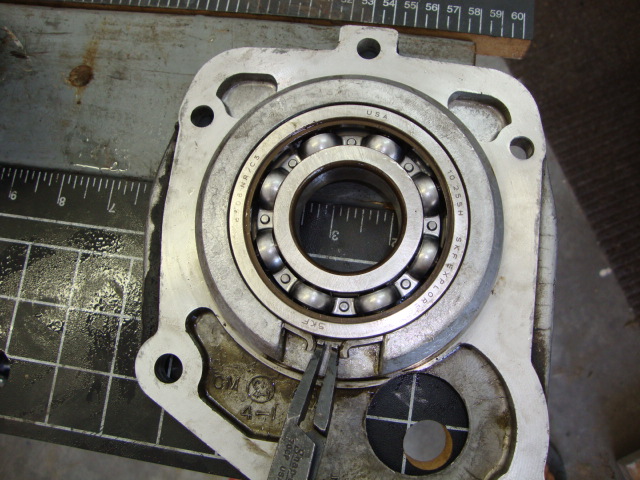
Or with the snap ring out you can use two flat blade screw drivers and insert the blades into the
outer race lock groove and pry out the main drive gear front ball bearing.
See groove in the 1st pic below where to insert the snap ring. You may need to tap the bearing
towards the front to make it easier to get the snap ring pliers in the space.
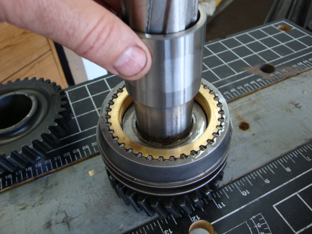
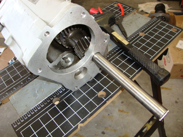
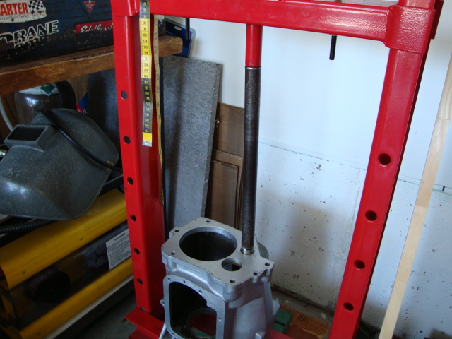
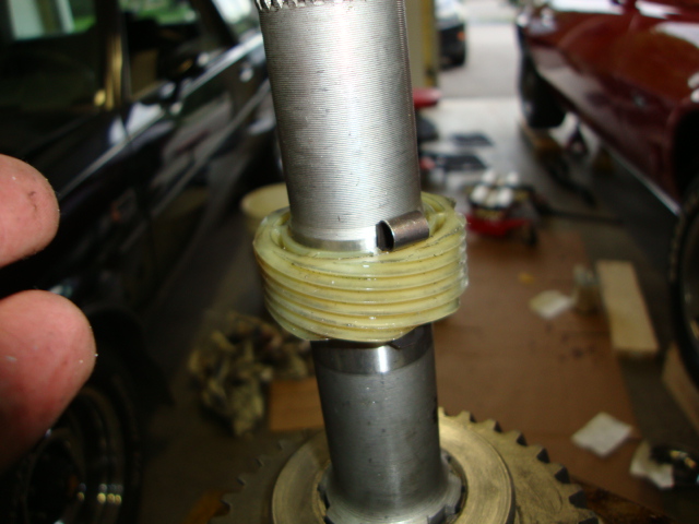
15. Counter gear: My course says to use a 7/16 x 8 inch brass punch and drive out counter gear shaft
from the front of the transmission. I never like to hammer on parts so since I have a press, I use it.
On the rear side, scribe a line across the 1/2 cut shaft where it locks into the rear bearing retainer.
Line up a piece of broomstick or a steel shaft that's smaller in diameter than the counter gear shaft
and press it out from the FRONT hole a couple of inches. It doesn't take much to break it loose.
 then you'll be able to pull it out with
your hand.
then you'll be able to pull it out with
your hand.
Note: If you don't have many miles on the tranny and are fixing another problem you can leave the washers
and needle bearings in place but you'll need to cut off a broomstick to the same length as the counter
gear and press it in place while the steel shaft is coming out so all the needle bearings don't fall out.
Then you can lift out the counter gear out of the case. The broomstick holds all the washers and needle
bearings in place. But the counter gear must come out so you can replace the thrust washers at each
end of the counter gear/case.
 <---
if your inserting the broomstick--->
<---
if your inserting the broomstick--->
BTW, I notice these needle bearings don't wear in diameter. I compared 2 sets and one set had over
70,000 miles on them with new GM bearings. Today, you don't know if your getting Chinese steel that'll
wear in no time and trash your tranny. So I'll leave that up to you.
On The Bench Overhaul
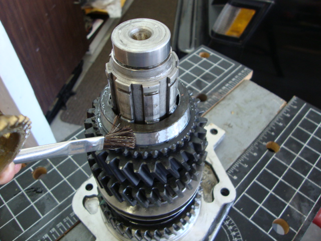
Use varsol and thoroughly clean all parts. Blow dry and inspect for damage, wear, deformity, breakage, nicks,
burns, and cracks. Check bushings for scone markings. Check bearings for roughness when turned. Replace parts
that exhibit to any of these conditions.
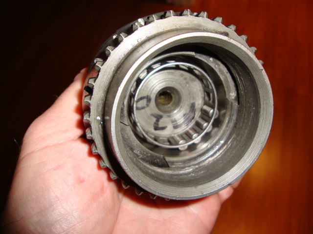
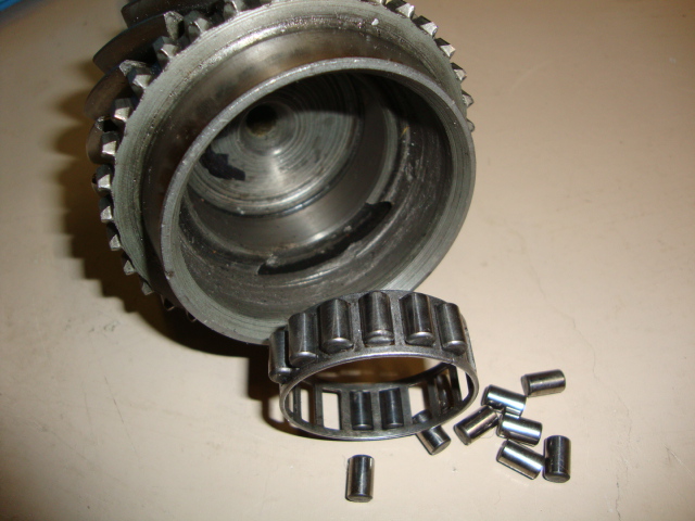
Main drive gear overhaul (Input Shaft 4th Gear):
Remove 17 needle roller bearings and cage from gear bearing boss. Perform prescribed checks and procedures.
Install bearing assembly. Use petroleum jelly to retain needle rollers to bearing boss.
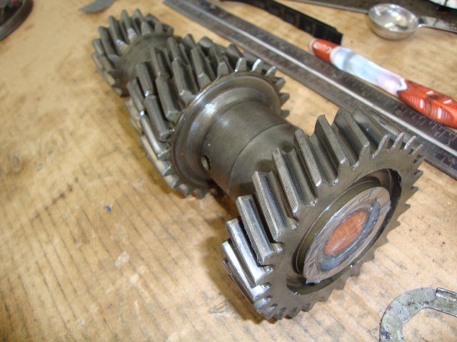
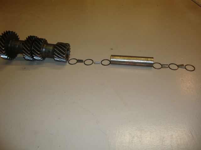
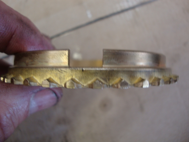
Counter gear and shaft overhaul:
Remove one hundred and twelve (112) needle roller bearings, (6) washers, and one roller
spacer tube. The steel roller tube I have is almost 5" long Part # 3912195.
Yours may be longer which would take 2 less washers. See instruction diagram below.
![]()
Perform prescribed checks and procedures
1. Install the metal roller spacer tube inside the counter gear.
2. Cut a broom stick the same length as the counter gear unless you have the tool and insert in the counter gear.
3. With 1 finger, push the broom stick and steel spacer tube up a bit and insert the 1st washer.
![]()
4. Use heavy grease to hold the bearings in place while you lay then in a row all the way around the broomstick.
5. Insert your 1st row of twenty-eight (28) roller bearings around the broom stick. Note the broom stick is used
to hold the bearings and washers in tack until it's time to place it in the trans case. Later as you insert the
counter gear shaft in the case through the counter gear, the broom stick will slide out without the bearings
falling out into the inside of the counter gear. Some people can do this without using a broomstick, but 1 little
nudge can cause them to fall down. I don't want to be doing this more than once so I use a broomstick.
6. Insert the 2nd washer.
7. Insert your 2nd row of (28) bearings.
8. Insert your 3rd washer. That's it for the one side.
9. Flip the counter gear to the opposite end and repeat steps 3-8.
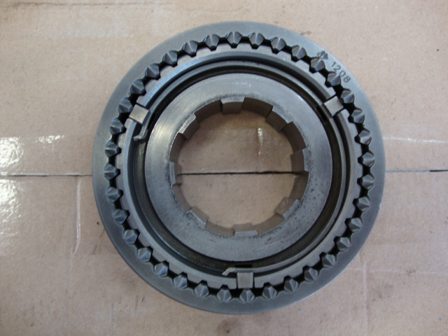
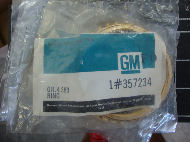
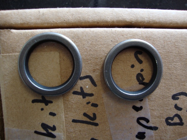
10. Replace the thrust washers part # 3864860 at each end. (#1 in the exploded diagram). Both thrust end washers
are mandatory with an overhaul. See top of page for washer pic.
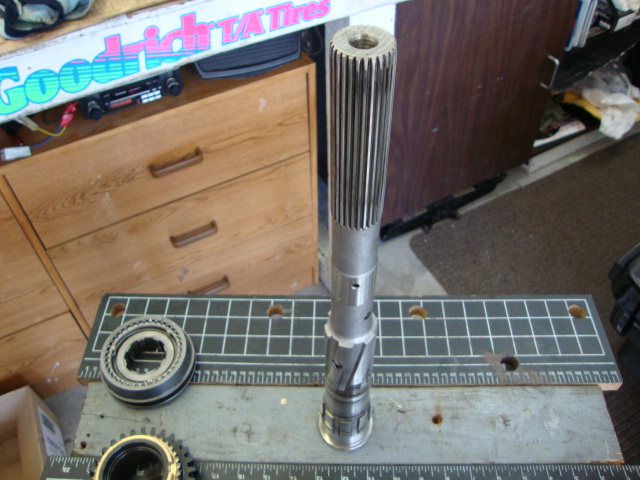
Mainshaft Overhaul:
1. Place assembly in vise (front end up). If you have a bench with a hole in it then use it.
2. Expand and remove 3-4 synchromesh retaining snap ring.
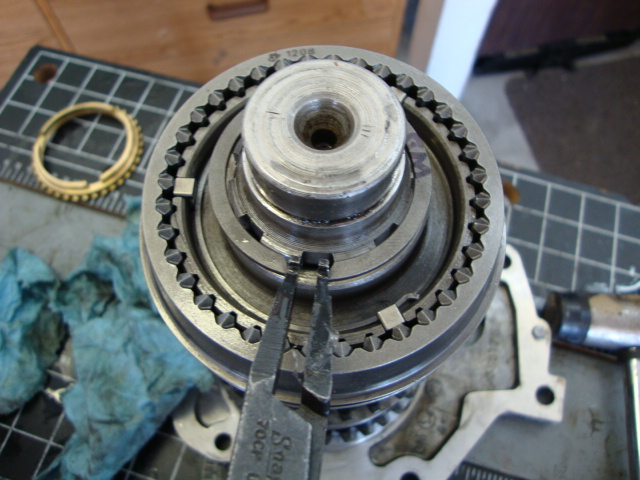
3. Remove 3-4 synchromesh assembly and 3rd gear.
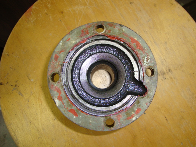
4. Turn assembly over and remove rear bearing retainer snap ring.
5. Tap retainer off of bearing outer race (bearing released by snap ring expansion).
Very Important Note: There are instances that occur during an overhaul operation where
the bearing and shaft, or sleeve, or retainer, fit is fairly tight. As a result, it may be
necessary to use a press to separate the assemblies involved.
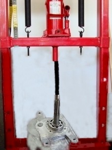
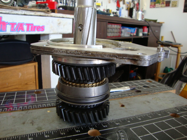
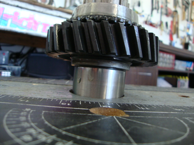
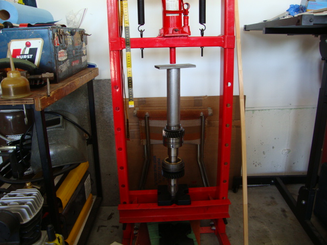
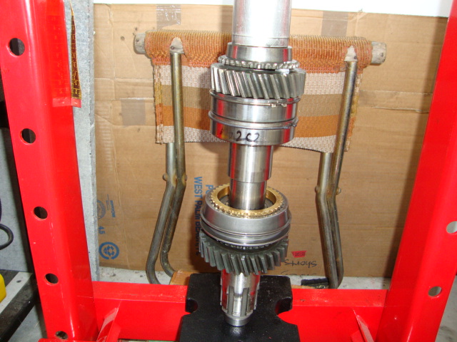
6. If it won't tap off then place the shaft in the press like this. I normally do this step anyways
to remove 1st gear, 1st gear sleeve, 2nd gear, and 1-2 sleeve/hub/synchro assemblies and lastly
the rear bearing retainer with the bearing. Don't forget to remove the snap ring in step 5 or nothing
will slide off. Also put something soft under the press to the shaft doesn't slam on the floor.
Also if you have a metal speedo gear on the tail shaft, measure the distance of it to the tail shaft end
so you remember how far it will need to be pressed back on. Some people heat it up to expand.
Then press everything off.
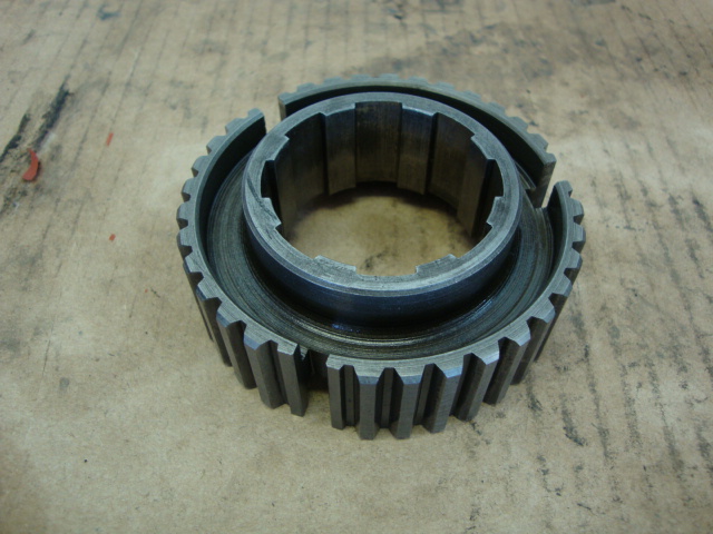
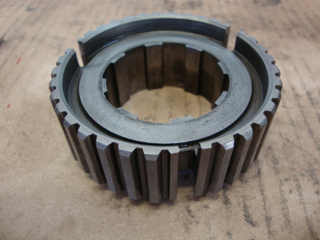
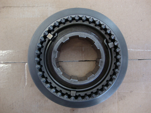
1-2 and 3-4 Synchromesh Assemblies:
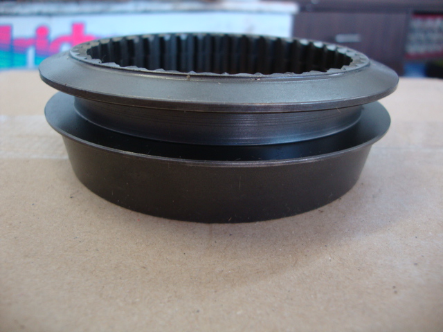
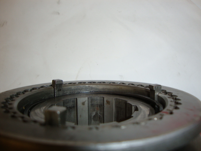
1. Remove clutch sliding sleeve off of clutch hub. Just push it through and the keys and locks will drop out.
Different views.
2. Remove keys, and tension springs. Perform prescribed checks and procedures. Note: synchromesh keys
and tension springs are replaceable.
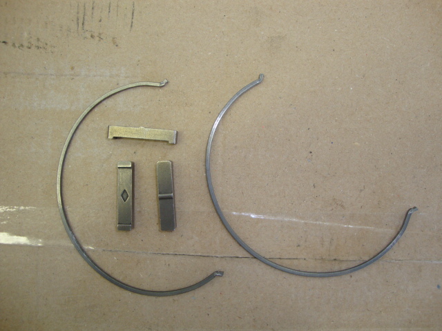
Do not replace the entire assembly because of failure of any of these parts. 3 keys and 2 spring locks
for 1-2 and 3-4 slider/hubs.
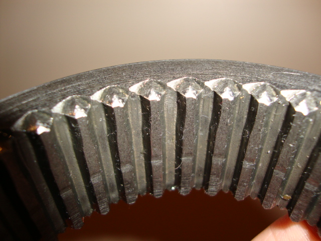
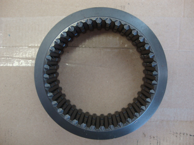
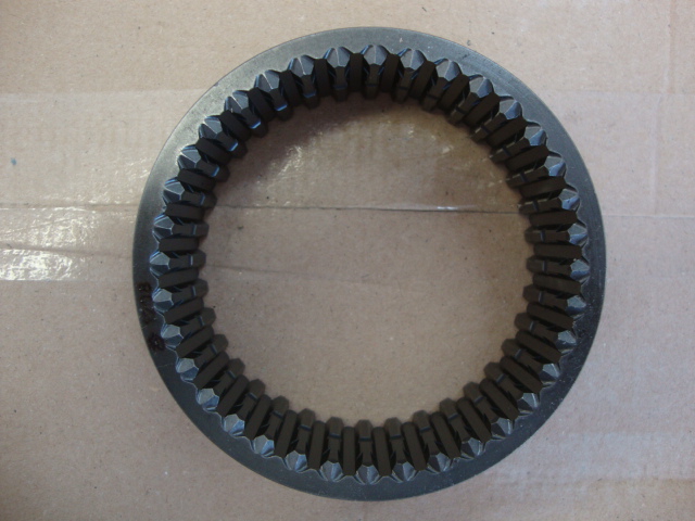
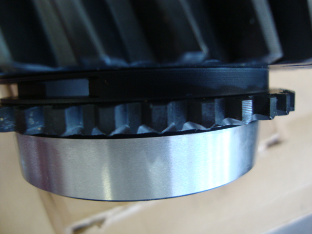
Slider with worn teeth
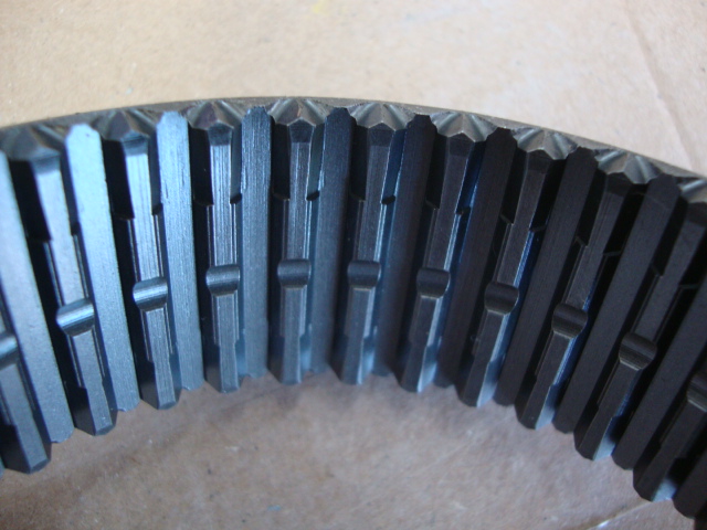
New Torque Slider
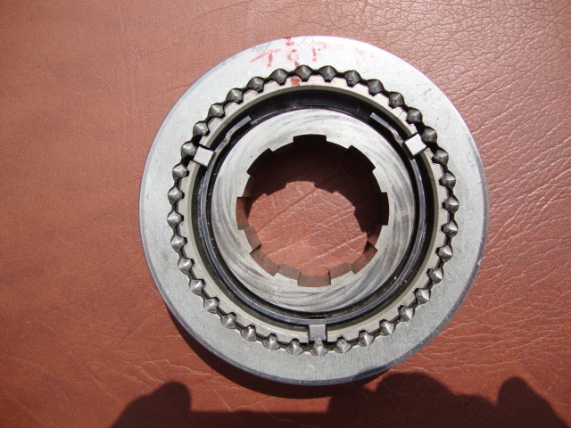
3. On the clutch hub, install tension springs, and retain keys with petroleum jelly. Push in keys
(collapse tension spring) and slide sliding sleeve over hub. Centre keys in hub detent.
New sliders with the same hubs. (hubs should not wear)
Stagger the tension springs (don't have them both in the same position for the front and rear).
keys position
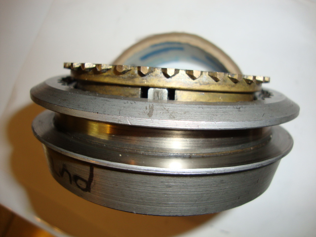
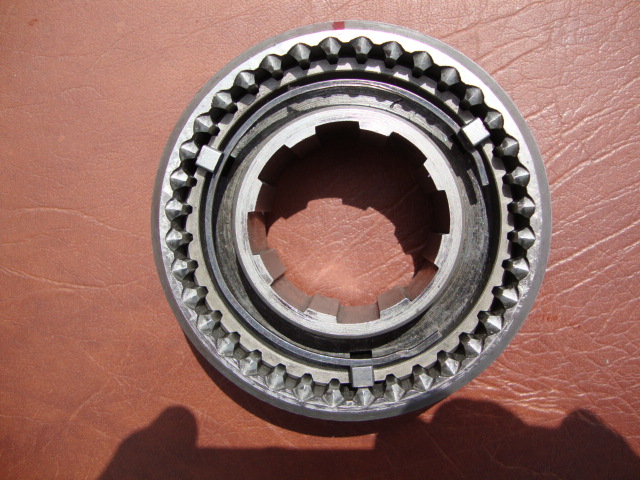
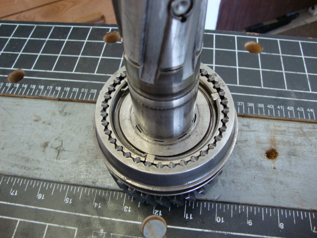
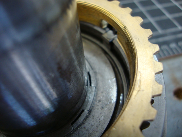
Note where the opening is on the brass synchro ring, This is where the keys line up in.
Note: sleeves position in relation to hubs 3-4 synchromesh sliding sleeve and clutch hub long
tapered ends both face the front of the transmission. (see pen)
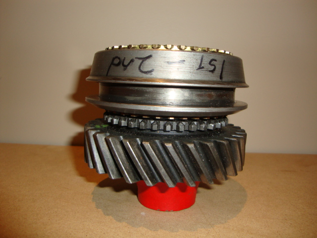
Note the tapered end of the 1-2 gear sleeve points to the rear and the 3-4 gear sleeve
points to the front.
Mainshaft Assembly
lube the syncho surfaces as the gears get installed and other sliding surfaces
1. Place mainshaft in a vise (rear end up) or in your work table hole.
2. Install 2nd speed driven gear.
3. Install 1-2 synchromesh assembly. Don't forget the synchros!
It will currently look like the M20 below on your shaft. Just pretend the mainshaft is there too in my photo.
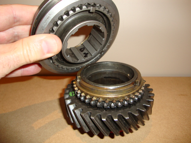
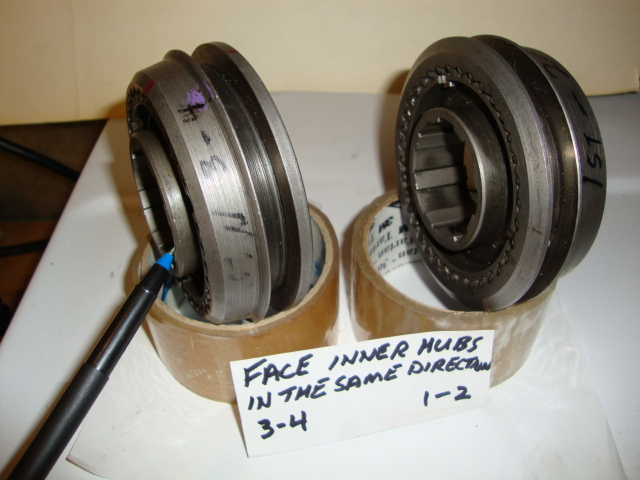
Remember which way the inner hub faces. If you forgot then go up to the last photo before Mainshaft Assemby
above a few lines.
4. Install 1st speed driven gear sleeve (it's a press fit sleeve - press into its proper location)
Here I'm using old parts to help press 1st gear sleeve down as far as it'll go.
I'm using 2 old bearings and a gear, plus a pipe and a sheet of 1/4" steel. When I took this pic my old bearing
that I was using as a pusher got tight on the shaft, so I had to press it off. So the fix was to use my old 1st
gear sleeve on top of the new one then all the other old parts I listed in the line above. It worked.
5. Install 1st gear with shiny synchro face facing down into the 1-2 synchro assembly like this.
6. Position rear bearing retainer over the bearing outer race and align snap ring with race lock groove.

7. Press fit rear bearing into its proper location on the mainshaft. Install selective snap ring. (.005 maximum clearance)
I used 2 old gears a pipe and a 1/4" piece of steel to press the bearing in place. It will stop when
you reach it's end of travel.

8. Expand and slide the rear bearing retainer snap ring to lock assembly in the groove. Note there are
several snap ring thicknesses in the kit to cover different shafts.
Trial fit the snap ring on the side of the groove before sliding the snap ring down the shaft.
If it doesn't easily snap into the groove after tapping it with a hammer then try a thinner one. It can't bind.

9. Turn mainshaft over (front end up)

10. Install 3rd gear.
11. Install the synchro for 3rd.
12. Install 3-4 synchromesh assembly on top of 3rd gear. Line up the cut outs in the synchro
to match the 3 locking keys in the sleeve/hub.
Note the orientation of the inner hub (facing to the front).
13. Install 3-4 synchromesh retaining snap ring. Don't install 4th synchro ring yet.

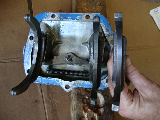
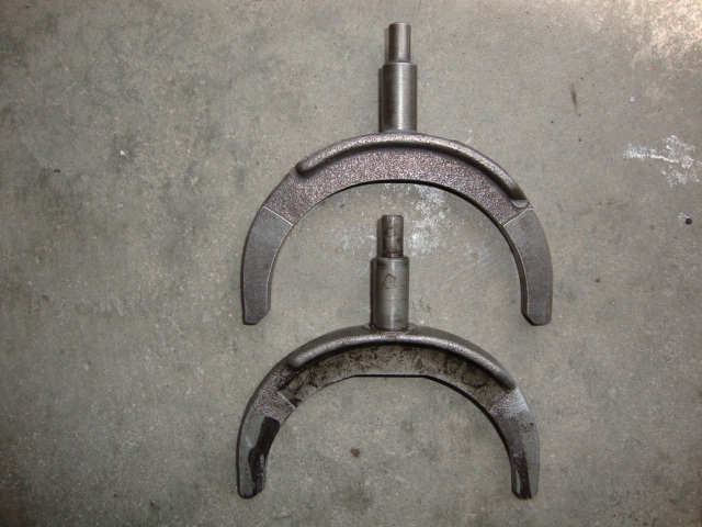
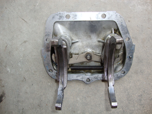
Side shifter cover assembly overhaul
(I only replace the 2 forks and the 2 seals)
Disassembly:
1. Remove detent cams retaining E ring.
2. Remove detent spring.
3. Remove 1-2 and 3-4 shifter forks.
4. Remove 1-2 and 3-4 shifter shafts and detent plates.
5. Remove 1-2 and 3-4 detent cams.
6. Remove seals and cover gasket using a small screwdriver. Don't touch the cover,
you don't want any scratches that can cause leaks.
7. Perform prescribed checks and procedures.
Side shifter cover assembly overhaul Assembly:
1. Install new shaft seals. I use a thin layer of high temp RTV on the edge so I don't have to worry about a leak.
Mine were sunk 3/32" below the top surface before I removed them so I used the same depth when I reinstalled them.
My reverse wasn't leaking so I left it.
2. Install 1-2 and 3-4 detent cams.
3. Install 1-2 and 3-4 shifter shafts and plates.
4. Install 1-2 and 3-4 shifter forks.
5. Install detent spring.
6. Install detent cams retaining E ring.
Transmission Assembly:
1. With case standing upright, use petroleum jelly or grease and retain 1 of the 2
countergear thrust washer to the front of the transmission case.
Note: washer tang fits in groove in case.
2. With all the needle bearings/ washers and broomstick inside the countergear,
insert the countergear in the case while holding the bottom so nothing falls out.
If you feel it's easier to do it with the case on it's side then do it that way. If
your building a Borg Warner 4 speed, then you need to just lay the countergear
on the bottom of the case. If you install the countergear shaft as in step 3 below
then you will never get the mainshaft in at step 9 below. Do step 9 first then do
step 3 below.
3. Turn case to rest on its front end and install rear countergear thrust washer
(slide into position of lock slot).
With the aid of tool J22246, align countergear and install its shaft. Or if using the
broom stick method as I did, insert the counter gear steel shaft from back to front
and push slowly, the broom stick will be replaced with the shaft. Position cut away
end of shaft to align with its mate lock slot on the rear bearing retainer.
(cut facing horizontal with the bottom of the case). The Borg Warner will have a
1/2 moon woodruff key.
4. Install (front) reverse idler gear thrust washer (has a tang).
5. Install (front) reverse idler gear in its location in case.
6. Using grease or vaseline, install the needle bearings/cage and drop into 4th gear cavity.
It's easier if you leave the cardboard ring on, then set in place, then push the cage down
then remove the cardboard ring.
7. Install 4th gear (input shaft) synchro ring and install input shaft in the case.
8. Install rear bearing retainer front gasket. I use Permatex 2 on both sides, GM didn't
use anything but I would.
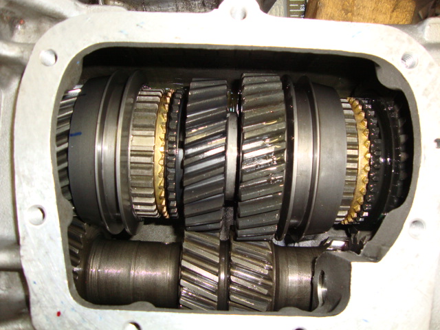
9. Place 3-4 synchromesh into 4th gear so you can get the 3-4 sleeve under the counter
gear that will be in the way when you drop the mainshaft in. So manuever it down on a
slight angle to get around the abstruction.
10. Maneuver step 8 assembly into the case. You need to line up the 3 synchro cut outs to
the 3 key cutouts on the input shaft syncro. I face a cut out towards the side cover so
I can see it when I slide the mainshaft down.
11. Align the rear bearing retainer dowel pins holes to the case dowel pins. Use a plastic
hammer and tap retainer on to case surface.
12. Install reverse gear (fork hub end must face the rear of transmission).
13. Install rear reverse idler gear into front reverse idler gear (align splines to install).
14. Install speedometer drive gear.
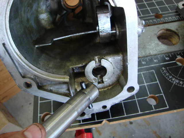
15. Insert reverse idler shaft assembly into the assembled reverse idler gear train.
16. Position roll pin vertical to align with its mate slot in the extension housing.
17. Install reverse idler rear gear shaft washer that has no tang.
18. Install extension housing gasket on rear bearing retainer (retain with petroleum jelly).
I like to use Permatex 2.
The above steps 15 to 17 can be skipped if you place the reverse shaft in as pictured
below and have the lock pin clocked to match the tail case.
19a. On extension housing, move reverse shifter to reverse position. Maneuver housing into
position over reverse gear. Observe the gear hub position in relation to its shifter fork.
You can use a flashlight shine it through the tail hole and see the inner reverse arm with
the slit and line up accordingly and push in reverse shaft to engage shifter fork into its gear hub.
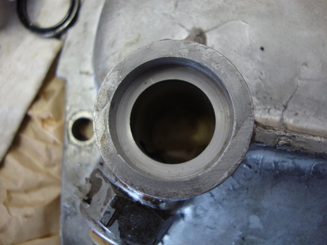
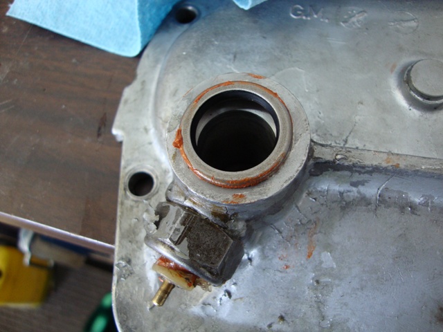
19b. If your tail shaft oil seal is leaking then this would be a good time to replace both the
bushing and seal.
Believe it or not, my 70 Muncie still has the original and is not leaking, therefore I won't
change it. Watch out for Chinese oil seals. Get them at GM or NAPA. I recently bought
the bushing just to have it before GM stock runs out. Below is a GM oil seal.
Rear extension bushing
1967-70 GM part # 6260048
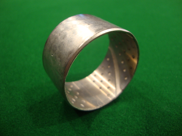
ID=1.50"
OD=1.63"
Length=.944"
1971-74 3987865
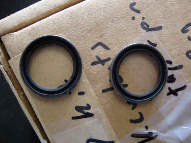
Rear extension oil seal
1967-69 ALL and 70 except HD part # 1386231
1970 HD and 71-74 ALL part # 8626009
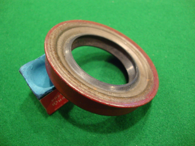
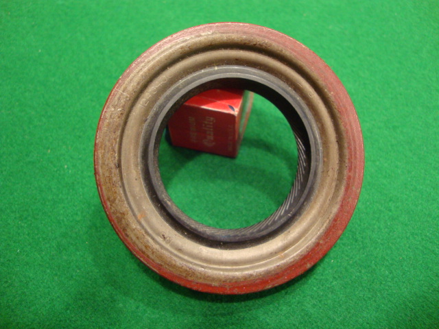
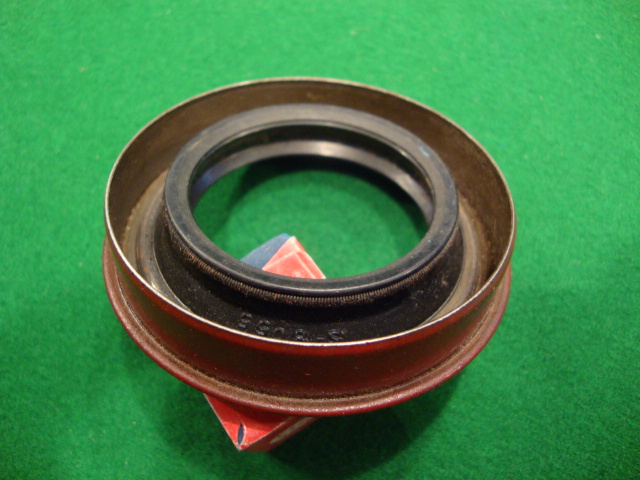
1386231 shown
20. Position extension housing on to rear bearing retainer and install 6 bolts. 3 upper bolts
(smaller) torque to 20 lb ft and 3 lower bolts to 30 lb ft.
Note: wait to install your speedo adaptor when the tranny is installed so you doesn't
get bumped around when you go to install the tranny into the clutch disc.
21. Align reverse shaft lock groove with extension housing boss lock pin hole. Install reverse
shaft lock pin. Don't hammer it in all the way yet.
isn't turning in the opposite direction then you didn't catch the groove on the reverse
arm into reverse gear. Remove the tail shaft and redo. Once corrected then hammer
the pin home.
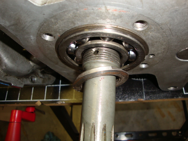
22. Shift reverse gear into neutral position. Install main drive gear front bearing, and its
outer race snap ring and tap bearing in place until the snap ring rests on the case.
23. Slide 1-2 synchromesh assembly into 2nd gear and 3-4 synchromesh assembly into 4th gear.
24. Install main drive gear retaining nut.
25. Using tool J-933, tighten nut counterclockwise to 40 lb ft. If you know how much force you
need on a bolt using a torque wrench then you should be able to guess the amount needed here.
26. Stake into the small hole to double lock the nut.
27. Install main drive gear gasket and retainer.
Note: oil passage cutaway in retainer. It must be aligned to the hole in the front case.
28. Install 2 French locks if you have them and (4) 3/8 x 7/8 bolts that secure the retainer
to the case and torque to 24 lb. ft. (use Permatex 2 thread sealer).
29. Slide 3-4 synchro assem into neutral. Leave transmission in 2nd gear from previous step.
If not in 2nd at this time then shift into 2nd so the side cover can go on easy.
30. Place shifter cover assembly into 2nd gear position to correspond with the 2nd gear
engagement of the transmission.
31. Maneuver 1-2 and 3-4 shifter forks into their respective sliding sleeve fork grooves and
install the side cover.
Install (7) 5/16 x 7/8 inch bolts that secure the cover to the case. Torque bolts to 22 lb ft.
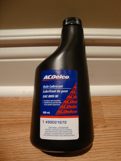
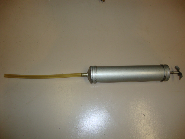
32. Fill with 80w-90 GL4 (not GL5) gear oil using a fill tool as in the pic below. Never use synthetic
in a Muncie. A Muncie needs the drag.
Then manually
THE END
DIAGS
|
PROBLEM |
CAUSE |
REMEDY |
|
Noisy
operation |
low
oil level
worn
bearings
broken
gear teeth |
fill
to proper level
replace
bearings
replace
gears |
|
Hard
to shift |
low
oil level
worn
bearings
worn
or broken synchromesh assemblies |
fill
to proper level
replace
bearings
replace
or overhaul synchromeshes assemblies |
|
Jumping
out of gear |
low
oil level
worn
bearings
worn
or broken synchromeshes
broken
gear teeth |
fill
to proper level
replace
bearings
replace
or overhaul synchromeshes
replace
gears |
.
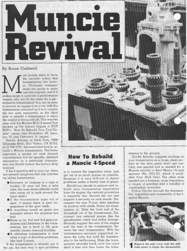
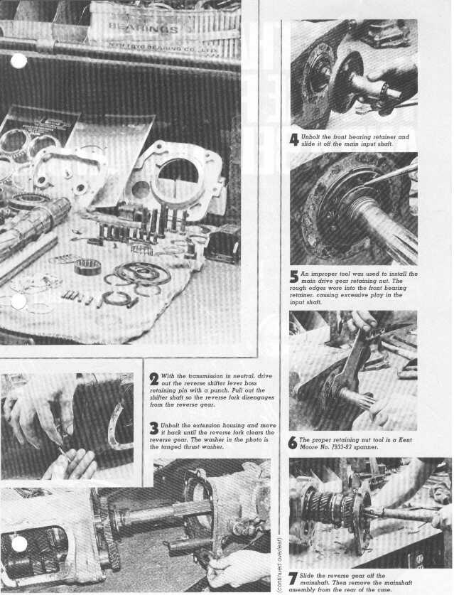
Muncie Rebuild Steps from a mag
![]()
![]()
![]()
For pics of what a worn and new gear and slider looks like click here